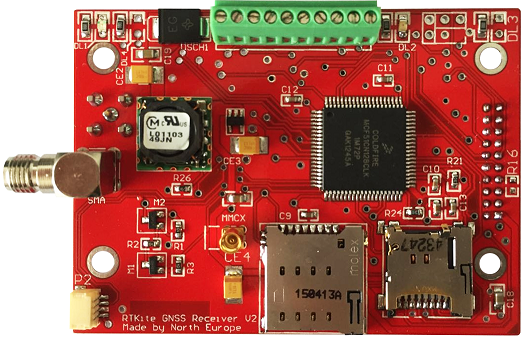
This manual covers the operation of the System-on-Module GNSS RTK receiver North RTKite V2.0 (Red Board)
User Operation Guide
Note: This manual does not explain the basic RTK concepts, if you require introduction, we recommend you to contact us or review the NOAA guidelines for RTK operation, or visit our main website for other kind of GNSS RTK receivers.
a.- INTRODUCTION
The North RTKite module is a GNSS RTK complete receiver designed to be the simplest to use and to be compatible with every OS platforms and communication protocols.
The standard configuration is able to receive Double Frequency GNSS signals (L1+L2, etc) of the following systems, depending on the setup: Navstar (GPS), GLONASS, Beidou (Compass), Galileo and internally process and solve RTK positions with millimetric accuracy.
The receiver is also capable to log Raw (RINEX) data to be Post Processed as DGPS.
The RTKite receiver has a mainframe that operates with the SmartOS Operative System on board, that is designed for a flexible and autonomous operation, and allowing to be upgraded to add new features over time on the same hardware platform.
This guide show the quick setup of the RTKite receiver system along with SmartOS Operating System in order to get immediate results.
This guide assumes that:
1.- You have a Controller device with Bluetooth and a Controller software compatible with NMEA sentences.
2.- You have basic knowledge of Geodesy, GNSS systems and RTK field operation.
3.- The only protocols that you require to operate are NMEA 0183, RTCM 3.x, CMRx or RINEX 3.x.
4.- “RTKite” stands for a fully featured GNSS RTKite receiver with or without UHF radiomodem, external radio-modem amplifier and the full set of accompanying software.
Important Note: For other options and detailed information regarding the SmaRTK receiver, the SmartOS software, CORS stations or 3rd-party RTK receivers, please review their particular manuals.
b.- RTKite Hardware Pinout
The RTKite unit have the following interfaces:
- Bluetooth Radio-Modem. This is the wireless operational interphase of the RTKite. It is used to receive the data when is configured as a Rover receiver as well as to send the configuration parameters of the receiver.
Important Note: The Bluetooth is permanently ON on the Configuration Mode and can be set as ON or OFF for the rest of the modes depending on your requirements.
- Indicator LEDs: Show several user interface data, described further on the Operation Modes.
- Micro-SIM Card Slot: Receives the Micro-SIM card of any celullar (mobile) network. The internal modem is unlocked, quad-band and requires that the Micro-SIM card has PIN code exactly “1111”. The Mobile Network is used on the NETWORK and AUTO-CASTER receiver modes for either transmitting or receiving RTK correction data.
- SMA Threaded Connector: Used to connect the corresponding GNSS Antenna as supplied by North. The antenna can be Helix or Patch Four-Element Surveying type, L1+L2 RTK.
- Push Button input: All user-input operations are made with this single button port (on the Wiring Connector 4: SW P1 and 5: SW P2) and the following inputs:
- Long-Press (3 seconds) used to: Enter the Configuration Mode.
- Short-Press (half second) used to: Arm the Event Trigger (i.e. for Camera logging)
Important Note: Instead a mechanical Push Button the operation could be controlled electronically by applying a 3.3VDC signal on PIN5. Float means Open and 3.3V means Closed.
- Wiring String Connector: Used to connect the Power, Transmitting, Receiving and Trigger according to the following Pinout:
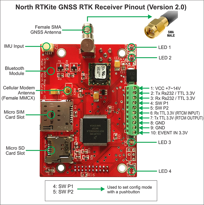
- UHF Radiomodem Data Link: For the locations where a Mobile Network (Cellular phone) is not available, then UHF Radiomodems can be used link the ground RTK GNSS Base receiver to the RTKite Receiver.
Important Note: The UHF Antenna should match the same UHF channel selected for transmission, to ensure proper range. North supplies by standard 460MHz +/-5 Antennas. There are other ranges available upon request.
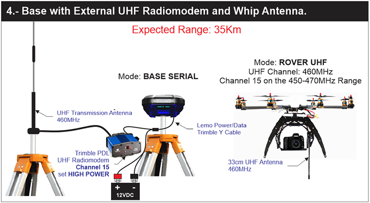
North supplies a wide spectrum 2W Tx/Rx Transceiver Radiomodem with a range from 410MHz to 470MHz that can be wired to the RTKite. For instructions on this please follow the UHF Module integration guide.
The UHF Module uses a MXC to TNC Pigtail to connect Receiving or Transmitting antennas to the internal UHF radio-modem. It is also used to connect the internal UHF radio-modem to the external U-Caster UHF radio-modem booster if the intention is to broadcast the RTK corrections.
- 7-Pin LEMO Connector: North can supply a standard LEMO connector used to connect the North-exclusive Y-Cable or a standard Trimble-Pacific Crest data cable. The Y-Cable can be used to charge to operate continuously the RTKite with external power, or to connect by USB to a PC to download recorded Static Data or to read real-time NMEA navigation data. The 7-Pin LEMO port is also used to connect and external Radio Modem.
Warning: The LEMO port can be used to connect external 12VDC power to the RTKite for continuous operation. The power source can be a car battery or a wall plug. However, crossing the polarity of the power source would result in immediate and permanent damage to the RTKite. This kind of damage is not covered by North's warranty. If you are not sure of what to do, please contact our support center.
Important Note: The LEMO Connector also can be used with a standard Serial cable for common RS232 interfaces.
c.- BASIC SOFTWARE OPERATION
- The RTKite GNSS RTK Receiver will operate as soon as the power is fed. It will automatically start to work on the previous Operation Mode, thanks to its resident flash memory. The input voltage should be between 7 to 12VDC.
- On the present version (V1.0 Red Board) the User interface consist of 2 leds, 1 green and 1 red that will indicate the most important features regarding the operation.
- The RTKite also has an special Configuration mode, that allows an external software tool call North SmartOS Config to setup all the details regarding data communications, operational mode, etc. This tool is available for Android, Windows and Linux.
c1.- STARTUP
1.- As soon as the RTKite module is powered on, both Red and Green LEDs will light during approximately 10 seconds while the internal OS is booted on.
2.- After the initial boot, the Red LED will flash intermittently white the operation mode is configured (previous operation mode that was set). The startup delay varies depending on the selected mode.
3.- After the startup is finished, then the module starts normal operation and the following indications will be shown:
a) Green LED flashes once every 5 seconds: The RTKite is receiving RTK corrections by Mobile Network Modem or UHF Radio Modem.
b) Green LED flashes twice every 5 seconds: The RTKite is receiving RTK corrections by Mobile Network Modem or UHF Radio Modem and the GNSS position is FIXED (millimetric solution)
c) Green LED is OFF: The RTKite is not receiving RTK corrections and is operation on Autonomous GNSS mode. (Metric accuracy or Submetric in case that an SBAS signal is present, i.e. WAAS, EGNOS, GAGAN, MSAS).
4.- If any of the DRONE modes are set, then the Event Marker logging can be Armed. The logging is used to record the position assigned to a trigger (Camera, Laser Distance Meter or other sensors). To arm the logging file use the “Push-Button” input closing the circuit of SW1 and SW2:
a) Push the button half second to Arm: The Red LED will flash once every 5 seconds, to indicate that the logging is armed.
b) When the survey is finished, push again the button half second to Disarm: The Red LED will stop flashing and is safe to turn off the RTKite.
c) The Logging will be saved as longitude, latitude and altitude coordinates (referred to WGS84 ellipsoid) on the SD Memory. The data can be extracted removing the SD card, or by Serial port using the PC data dumping tool or by Bluetooth (longer time) using the Config tool.
Important Note: Do not turn off the RTKite before Disarming the Logging of events, otherwise the Log would be lost.
Important Note: To download the Logged Data from the SD card by Bluetooth or Serial cable, the RTKite must be in Configuration Mode.
c2.- CONFIGURATION
- To enter the Configuration Mode, Long-press the button (3 seconds), and the Green LED will be turned ON permanently to indicate that the RTKite will accept setup orders.
- Connect the PC or Android device to the Bluetooth of the RTKite module, pairing the units previously, and use the North SmartOS Config tools to setup the RTKite.
- To exit the Configuration Mode, Long-press the button again (3 seconds), and the Green LED will be turned OFF and the RTKite will return to the selected Operation Mode.
- To turn off the RTKite, disconnect the power input.
Important Note: The options that are set on the receiver are recorded on the physical memory and will be kept even if the batteries are fully discharged or removed.
- To connect a PC or Android Device by Bluetooth, set the parameters of the Controller Operative System to connect to a COM port and, if asked, insert the code “1234” to Pair with the RTKite's Bluetooth.
c1.- FIRMWARE UPDATE
1) Download the updater of the latest version from the following link and run it: RTKite Latest Firmware
2) On the RTKite board Connect pins 2 and 3 (TX and RX) to a PC with a USB to TTL3.3V or Serial RS232 converter (depending on the RTKite board version that you own). The Tx-Rx and Rx-Tx signals should be crossed and GND must be connected.
3) Power up the RTKite module while the Mode push button remains pressed during 15 seconds. The red LED will flash during this time and the receiver will be on Update Mode.
4) With the COM port already connected, on the Updating software click on the UPDATE button.
Important Note: The computer MUST be connected at internet during this operation.
d.- SYSTEM OPERATIVE MODES
- To set and save the operation modes, firstly enter the Configuration Mode, as described on “c2”, and use the North SmartOS Config setup tool to select the desired mode.
Important Note: It is recommended to set all the operation parameters at once as they are saved on the RTKite and will simplify operation, saving setup time.
The RTKite can operate on the following Operation Modes:
1.- DRONE NETWORK.
- Mode to control Autopilot, capture pictures and triggers, and calculate RTK solution from corrections sent from a public CORS station by 4G Mobile Network.
Requires: SIM Card, APN data from Mobile Network, CORS access permission.
Functions: GeoTagging saved on SD Card, RAW data saved on SD Card, Navigation data,
2.- DRONE AUTOCASTER
- Mode to control Autopilot, capture pictures and triggers, and calculate RTK solution from corrections sent from a North SmaRTK, RTKite or Punto Ground base by 4G Mobile Network by the Autocaster system.
Requires: SIM Card, APN data from Mobile Network, AutoCaster access permission.
Functions: GeoTagging saved on SD Card, RAW data saved on SD Card, Navigation data,
3.- DRONE UHF
- Mode to control Autopilot, capture pictures and triggers, and calculate RTK solution from corrections sent from a North SmaRTK, RTKite, Punto or any brand RTK Ground base by UHF radiomodem.
Requires: RTCM3.X corrections on Pin6 (3.3V TTL), UHF Module (optional).
Functions: GeoTagging saved on SD Card, RAW data saved on SD Card, Navigation data,
4.- ROVER NETWORK
- Mode to operate as land suveying receiver calculating RTK solution from corrections sent from a public CORS station by 4G Mobile Network.
Requires: SIM Card, APN data from Mobile Network, CORS access permission.
Functions: RTK Positioning in NMEA by Bluetooth.
5.- ROVER AUTOCASTER
- Mode to operate as land suveying receiver calculating RTK solution from corrections sent from a North SmaRTK, RTKite or Punto Ground base by 4G Mobile Network by the Autocaster system.
Requires: SIM Card, APN data from Mobile Network, AutoCaster access permission.
Functions: RTK Positioning in NMEA by Bluetooth.
6.- ROVER UHF
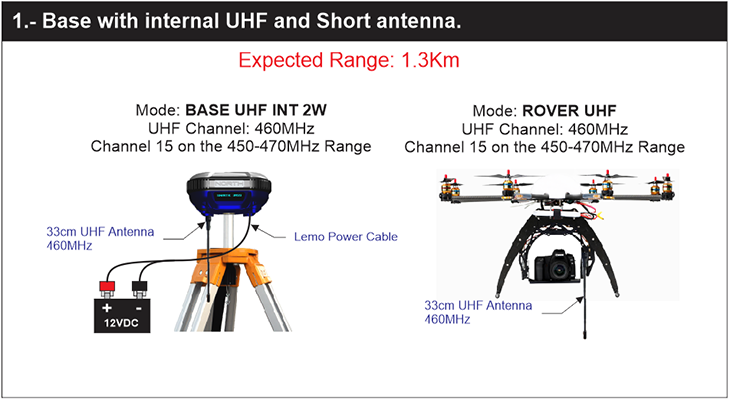
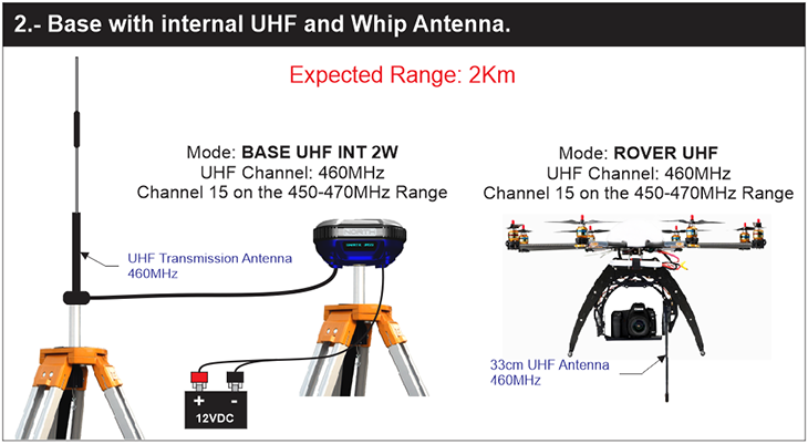
- Mode to operate as land suveying receiver calculating RTK solution from corrections sent from a North SmaRTK, RTKite, Punto or any brand RTK Ground base by UHF radiomodem (optional module).
Requires: RTCM3.X corrections on Pin6 (3.3V TTL), UHF Module (optional).
Functions: RTK Positioning in NMEA by Bluetooth.
7.- BASE AUTOCASTER
- Mode to broadcast RTK corrections as a base by 4G Mobile Network by the Autocaster system.
Requires: SIM Card, APN data from Mobile Network, AutoCaster access permission.
Functions: Broadcast RTK RTCM 3.X Corrections by Mobile Network.
8.- BASE UHF
- Mode to broadcast RTK corrections as a base by UHF Radiomodem (optional module).
Requires: UHF Module (optional).
Functions: Broadcast RTK RTCM 3.X Corrections by UHF Module (optional)
9.- BASE SERIAL
- Mode to broadcast RTK corrections as a base to an external UHF Radiomodem or CORS station server.
Functions: Broadcast RTK RTCM 3.X Corrections by Serial Port (RS232).
10.- PPK RECORDING
- Mode to record RINEX data for further Post Processing DGPS solutions.
Meaning of Operation Mode Requisites:
Requisite
Description
SIM
Micro SIM Card with 1111 PIN and Internet Data access enabled.
APN
Phone company data access. Needs APN Name, User and Password.
CORS
Permissions to acces a Continously Operating Reference Station NTRIP. Needs: URL or IP, Port, User, Password, Stream, Requires Location (Yes/No)
AutoCaster
North AutoCaster Permissions.
Needs URL and Port.
RTCM on Pin6
RTCM 3.1 Input (RTK Differential Corrections) By UHF external module on PIN6 with TTL logic protocol and 3.3VDC.
Meaning of Operation Mode Functions:
Functions
Description
GeoTag on SD
Logging of the geodetic position coordinate on the SD card on sync with the camera Flash trigger. 0-3.3VDC pulse on PIN10.
RAW on SD
Looging of RAW data on the SD card for DGPS Post-processing.
Navigation
At the moment there are 3 modes. All are output on Pin 2 @ 115,200bps, with RS232 Serial protocol:
1.- Generic NMEA 10Hz
2.- Pixhawk NMEA 5Hz
3.- Pixhawk Binary 5Hz
For modes 2 and 3 the Pixhawk requires update to a North custom firmware version,
RTK Positioning.
Millimetric RTK NMEA output by Bluetooth, with RCM, GGA, GSA and GST sentences.
d1.- NETWORK MODES
d1.1.- To operate on Network Mode you will require:
d1.1.1.- Access data to your local CORS RTK correction provider. The RTKite will accept any CRM or RTCM format. The CORS server service should provide you with:
CORS IP Address or Web Address
CORS Server Port
CORS User
CORS Password
CORS Stream
d1.1.2.- A Micro-SIM card with active Internet connection. The SIM has to have its PIN set to 1111.
d1.1.3.- The Access Point Name (APN) data of your Mobile Network provider. You will require:
APN Name
APN User
APN Password
d1.1.4.- The “North SmartOS Setup” Software to set the parameters into the RTKite. This can be done on by Bluetooth or Cable. You can use the Windows Mobile, Windows PC, Android or Linux versions. We recommend you to do it by Bluetooth with the controllers approved by North.
Important note: If the RTKite is set on any mode that requires the Mobile Network connection, in case that the network settings are not set or the SIM card is missing or not working properly, the receiver will lock most functions while it looks for the Network. This operation can delay at most 5 minutes, please allow the receiver to stop looking for connections to continue.
d2.- AUTO-CASTER MODES
d2.1.- To operate on Auto-Caster Modes you will require:
d2.1.1.- Connection data to the Auto-Caster system. Your North Representative or North's Support Center will provide you with:
Auto-Caster Web Address
Auto-Caster Ingoing Port (For the Base)
Auto-Caster Outgoing Port (For the Rovers)
Auto-Caster Password
d2.1.2.- A Micro-SIM card with active Internet connection. The SIM has to have its PIN set to 1111.
d2.1.3.- The Access Point Name (APN) data of your Mobile Network provider. You will require:
APN Name
APN User
APN Password
d2.1.4.- The “North SmartOS Setup” Software to set the parameters into the RTKite. This can be done on by Bluetooth or Cable. You can use the Windows Mobile, Windows PC, Android or Linux versions. We recommend you to do it by Bluetooth with the controllers approved by North.
Important note: If the RTKite is set on any mode that requires the Mobile Network connection, in case that the network settings are not set or the SIM card is missing or not working properly, the receiver will lock most functions while it looks for the Network. This operation can delay at most 5 minutes, please allow the receiver to stop looking for connection to continue.
d3.- SHORT RANGE UHF MODES
d3.1.- Setting of an RTKite as Base in the UHF Short Range Mode.
Important note: There are 48 preset channels of the RTKite, that match those of Pacific Crest brand Radio-modems. In case that you need to setup a different channel, please contact your North Support Center.
Important note: The default correction format is RTCM3, however it can be changed to match other receivers. In case that you need to setup a different format, please contact your North Support Center.
Important note: The power draw of the internal radio is high, and will reduce the battery life importantly. North recommends that you use the Bases of any UHF mode plugged to an external power line of 12VDC if the Base is intented to operate full working days.
Important note: One single UHF Base can broadcast to an unlimited number of UHF Rover within its transmission range.
d4.- LONG RANGE UHF BASE - ROVER MODES
d4.1.- Setting of an RTKite as Base in the UHF Long Range Mode.
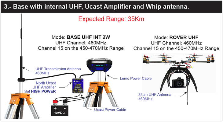
d4.1.1.- Connect the North U-Caster UHF Booster to the RTKite TNC Port with the supplied TNC Coaxial cable. High (45W) or Low (25W) power can be selected depending on the requirement.
d4.1.2.- Connect the North U-Caster UHF Booster to the external 12VDC power line.
Warning: The U-Caster LEMO port is used to connect external 12VDC power to the Radio-modem mainframe for continuos operation. The power source can be a car battery or a wall plug. However, crossing the polarity of the power source would result in immediate and permanent damage to the U-Caster. This kind of damage is not covered by North's warranty. If you are not sure of what to do, please contact our support center.
Warning: Make sure that all connectors of the U-Caster unit are connected before plug the power to avoid power spikes.
Important note: There are 48 preset channels of the RTKite, that match those of Pacific Crest brand Radio-modems. In case that you need to setup a different channel, please contact your North Support Center.
Important note: The default correction format is RTCM3, however it can be changed to match other receivers. In case that you need to setup a different format, please contact your North Support Center.
Important note: The power draw of the internal radio is high, and will reduce the battery life importantly. North recommends that you use the Bases of any UHF mode plugged to an external power line of 12VDC if the Base is intented to operate full working days.
Important note: One single UHF Base can broadcast to an unlimited number of UHF Rover within its transmission range.
Important note: The Range of the 45W radio is of about 37Km in direct view with both Tx and Rx antennas at 2m above the ground. Please review the following graph as reference:
************************
If longer ranges are needed, the Tx antenna should be placed on the highest possible position.
d6.- STATIC POST PROCESSING MODE
d6.1.- Setting of an RTKite as Raw data logger for Post-processing.
Important note: Two receivers are required at least to do a Postprocessing DGPS. The following process is the same for both receivers.
d6.1.1.- Turn on the RTKite
d6.1.2.- Go to the “RECEIVER MODE” Sub-Menu and enter with a Long-press
d6.1.3.- Select the “PPS RECORDING mode and Long-press to set it and exit the Sub-Menu.
d6.1.4.- Go to the “QUIT SETUP” and Exit the Main Menu.
d6.1.5.- On the Main Screen the “PPS RECORDING” mode would be displayed and the “RDY” sign would indicate that the system is Ready to start recording.
Important note: For Static recording it is important to start the log with most satellites locked. Please allow the receiver a few minutes to lock all the satellites in view. You can follow this process on the satellite indicator of the Main Display.
6.1.6.- Please allow enough time for enough satellites to lock and when you are ready to record give a Short-press to the button. After a short delay of 3-5 seconds the display will change from “RDY” to “REC” in order to indicate that the Logging has started.
Important note: For Static recording the logging time should be of at least 15 minutes and the minimum recommended time is that of 30 minutes to insure the high accuracy of the Post-processing.
6.1.7.- When you desired to finish recording, Short-press the button and the display will change from “REC” to “RDY” in order to indicate that the Logging has stopped.
Important note: Each time that the button is short-pressed while on the Main Screen of the Static PPS mode, a new file will be created. Each file will have a name that includes the current Date and Hour, plus the basic Filename that can be set on the SETTINGS Sub-Menu, with the North SmartOS Setup Software.
d6.2.- Downloading, Converting and Post-Processing the raw data.
d6.2.1.- To download the recorded data, connect the receiver to a PC with the USB or Serial cable.
Important Note: The RTKite needs to be on the Configuration Mode in order to be able download data.
d6.2.2.- Allocate on the PC Operating System with COM port is the RTKite connected to.
d6.2.3.- Open the “North RTKite Config” software, select the COM port that correspond to the RTKite and click on the “Connect” button.
d6.2.4.- Select on the “North RTKite Config” software the destination directory for the files and press the “Download PPS” Button.
d6.2.5.- Wait until the download finished, it may take several minutes. When is successful a message will appear showing the correctly downloaded NOR files.
***************************************
Important Note: When the files are downloaded, you will have NOR raw files that are compatible with Novatel Raw files. You can use Post-processing tools compatible with Novatel or you can convert to RINEX with the included tools to post-process as RINEX files.
d6.2.5.- When the work is finished, you can Turn Off the RTKite. The configuration is saved and will remain the same when is turned on.
d6.2.6.- To convert the downloaded Raw NOR files, open the NOR to RINEX converter tool. Firstly click the “Auto Detect option” and the “*.*” File type.
d6.2.7.- Select the files to convert, the destination directory, and press the “Convert” Button. The resulting files will be standard RINEX Observations.
************************
d6.2.8.- Once the RINEX files are obtained, they can be Post-processed in any software. In this example the Compass Solutions. Create a new project:
***********************
d6.2.9.- Import at least two Static RINEX files into the project:
*********************
d6.2.10.- Set the parameters of the files according to your jobsite surveying:
*******************
d6.2.11.- Click “Process All” to process all the Static Baselines:
******************
d6.2.12.- Go to the Report section and read the results:

